Installing a CO Line Trunk Daughterboard in the NEC SL2100
Installing a CO Line Trunk Daughterboard in the NEC SL2100
This tech tip covers the procedure for mounting an NEC SL2100 3 Port CO Line Card on to the CPU Card inside the Main Chassis.
Notes
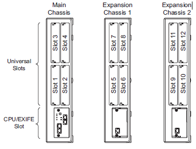
- The procedure is being explained is for slot #1, however, the other slots are used in the same manner.
- Circuit boards are not hot swappable. Do not remove or install from the chassis while powered up.
- Do Not Power on until all installations have been completed.
- If Expansion Chassis are installed, turn the power on/off in the order of Expansion 2 Chassis, Expansion 1 Chassis and then Main Chassis.
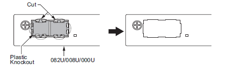
- For your safety, smooth the cut edges after removing the plastic knockout.
- Use PCPro to obtain a backup of the system database.
Slot Location
Each 4KSU-C1 has four universal slots for station, trunk and optional boards excluding the CPU/EXIFE slot. However, Slots 4,8,12 do NOT Support any type of Multiline Terminals. Analog extensions (and any type of Trunk card) will work. For the slot location in the 4KSU-C1, refer to the figure below.
Mounting the CO Line Trunk Card
1. Turn off power to the system.
2. Loosen two screws and pull out the 082U/008U/000U.
3. Cut and remove specified Plastic Knockouts on the 082U/008U/000U board.
4. Mount the 3COIDB/1PRIDB board onto the 082U/008U/000U board using one screw.
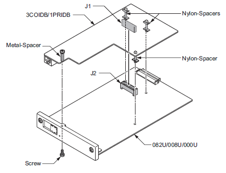
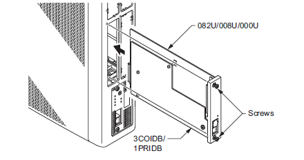
5. Insert the 082U/008U/000U board with 3COIDB/1PRIDB board in the guide rail of chassis and push it securely into the Chassis.
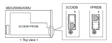
How to Recognize the Type of Trunk Daughter Board
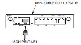
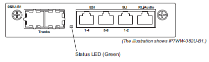
The type of installed Trunk Daughter Board can be easily recognized by checking the position of RJ61/RJ45 connectors at Front Panel, without removing the installed board from Chassis.
Cabling the CO Line Trunk Daughterboard
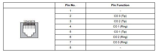
This IP7WW-3COIDB-C1 board provides one RJ-61 connection for CO lines.
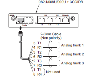
The following table shows the pin-outs for the RJ-61 cable connector for CO connection.
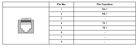
This IP7WW-1PRIDB-C1 board provides one RJ-45 PRI/T1/E1 connection.
The following table shows the pin-outs for the RJ-45 cable connector for PRI/T1/E1 connection.
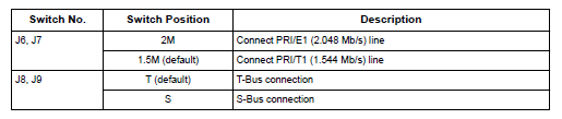
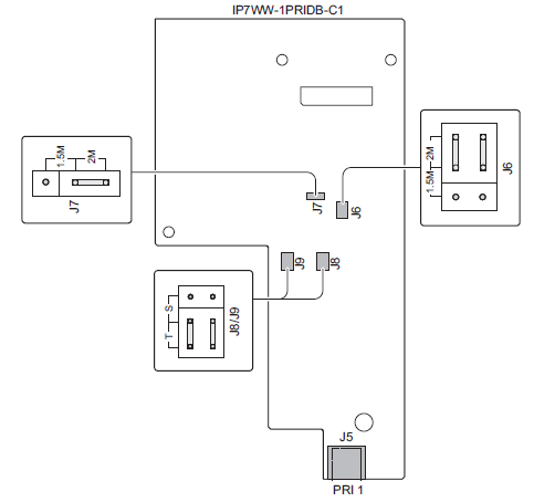
PRI Switch Setting
1. Set the switches J6 to J9, according to diagram below. In most cases the default value is acceptable.
2. Connect the cables from the NT1 Network Termination cable to the J5 connector on the 1PRIDBC1 board.
3. Assign whether the board works as PRI/T1 by PRG10-51-01.
With Normal operation, Status LED on the base board flashes (100 ms On/100 ms Off) green.
LED Indication
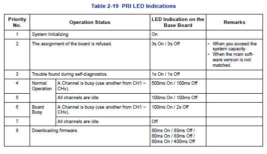
A Status LED is available only for the base board (082U, 008U, 000U). The daughter board (3COIDB, 1PRIDB) does not have the status LED, therefore the Status LED on base board is used in common for LED indications related to the daughter board.
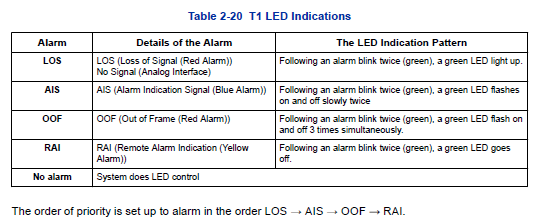
The order of priority (No.1 ~ 8) is set up to each status and when more than one status has occurred, the highest priority LED indication pattern (status) will be indicated. See the table below.
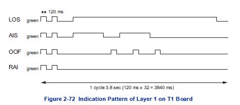
T1 Alarm Mode
Refer to the following figure for LED pattern information. LED indications for the T1 are listed below.