Configuring a T1/PRI Card on the NEC SL1100
Configuring a T1/PRI Card on the NEC SL1100
This Tech Tips demonstrates how to configure a T1/PRI card, including DID translations and DID Mode Switching. This tip applies to the NEC SL1100 Phone System only.
Get Connected
This Tech Tip requires access to the phone system using NEC PCPro Programming Software. To download the latest version of PCPro or for instructions on how to connect your computer to the phone system, please read the following: How to Connect to the NEC SL2100 or SL1100 Phone System for Programming.
PCPro Programming Steps
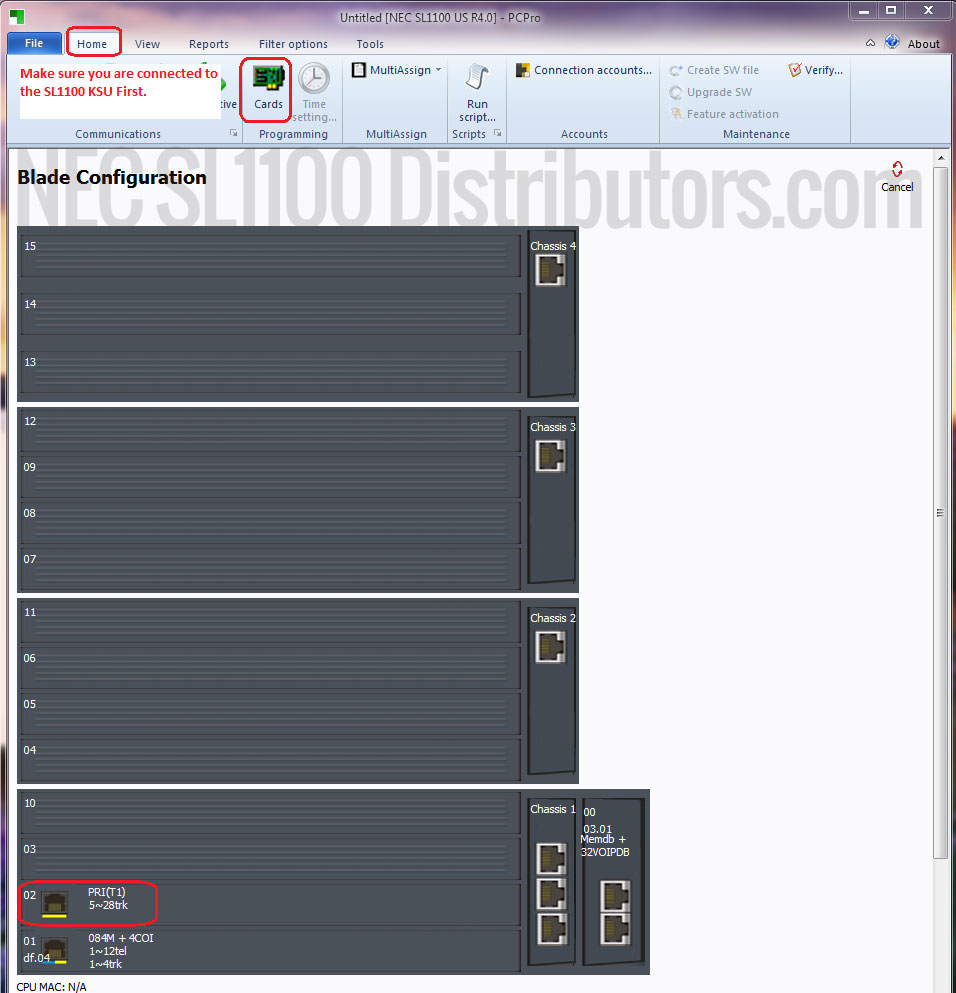
Find out what ports are assigned to your PRI trunks. You can do this by clicking on “Cards” under the “Home” tab in PCPro
On our example system above, the PRI trunks are 5~28. Yours may be different. Make a note of your configuration.
In Advanced View, go to Program 14-05 Trunk Groups.
In 14-05 you will change the POTS CO trunks (01-04) to group 2. This will isolate the unused CO trunks from the T1/PRI Trunks now assigned to Trunk Group 1.
Navigate to Program 22-02 Incoming Call Trunk Setup.
Switch your T1/PRI trunks to DID for all Modes that you will be using. In our example we set all T1/PRI trunks to DID for all 8 modes. You will see below that our Trunks 1-4 (Trunk Group 2) will be left at the “Normal” default settings.
Now go to Program 22-09 DID Basic Setup:
Here we will configure the number of dial-in receive digits (last amount of digits on an incoming line) that the phone system will look at in order to perform DID translations.
Go to Program 22-13 DID Trunk Group to Translation Table Assignment.
In this program we link Night Modes 1 through 3 for Trunk Group 1 to their respective DID Translation Tables.
Now go to Program 22-10 DID Translation Table Area Setup.
Here we setup different translation table areas. We can setup common translations for all tables as well as translations specific to the translation table area.
Now go to Program 22-11 DID Translation Table.
In this program block we setup DID entries for the phone system. Depending on the mode to translation table assignment in program 22-13 and the translation table area setup in 22-10. The phone system determines where an incoming DID should be routed.
For our first entry, we will setup an entry that will route fictitious phone number 999-313-4110 to Bill at Extension 108. And since Table Entry 1 is a part of the 1st Translation Table Area, it will be active no matter which mode the phone system is in. In other words, this translation will always be in constant effect.
Next, let’s setup an entry that will route fictitious phone number 999-313-4100 to entry 101. This will ring a group of phone(s) first and then overflow to an auto attendant. Entry 101 will only be active when the phone system is in Mode 1.
We will now setup entry 201 as our Night time Main number DID. This Entry will only be active when the system is in Mode 2.
Lastly, we will now setup entry 301 as our lunch time main number DID. This Entry will only be active when the system is in Mode 3. It will route the call immediately to a routing mailbox that is attached to Department Group 3105 in place of its group mailbox using the Default Voicemail Pilot Number of 3999 (Ex. VM Pilot Number 3999@Department Group Mailbox 3105).
Now go to Program 47-03 InMail Group Mailbox Options.
In 47-03 we reconfigure Group Mailbox 05 – 3105 to Routing Mailbox 3. This change will allow DID entry 301 answer with Routing Mailbox 3.
Now go to Program 21-12 ISDN Calling Party Number Setup for Trunks.
This program will allow us to configure what number is sent out when an internal user makes an outgoing phone call on a per trunk basis. For our example, I have configured all trunks to display the fictitious main phone number for our clients business.
Now go to Program 21-13 ISDN Calling Party Number Setup for Extensions.
This Program will allow us to pair an outgoing caller id number with an extension. We will configure Extension 108 to send out its corresponding DID number which was assigned in DID translation table 1. Once again we are using a fictitious number
NOTE: A number assigned to an extension in this program will override any numbers assigned in 21-12.
Now go to Program 12-01 Night Mode Switching Setup.
In 12-01 we will make sure that 02 – Automatic Night Mode Switching is enabled. You can leave 01 – Manual Night Mode Switching enabled as well.
Go to Program 12-07 Night Mode Name Setup.
In 12-07 we will assign names to Mode 2 and Mode 3 which will show up on the screens of all phones connected to the system depending on the mode the system is currently in per the applied schedule created earlier.
Go to Program 12-03 Weekly Night Mode Switching.
This program determines which service pattern is used for which day of the week. We only use Night Mode Service Group 1 so only the first row is being looked at by the system. Monday through Friday are using service pattern 1 while Saturday and Sunday are using pattern 2.
Go to Program 12-02 Automatic Night Service Patterns
In this program we schedule the mode switching by assigning different modes to different hours of the day. The first or default time schedule pattern that is opened when entering this program is always time schedule pattern 1 which is shown in the top right corner (this is our schedule pattern for Monday to Friday as programmed in 12-03 Weekly Night Mode Switching)
• In this program item 01 will always start at midnight or 00:00 and end at the time the next mode change is to occur. In our case we want the phone system to switch from night mode to day mode at 8am or 8:00. Therefore midnight to 8am the system is in mode 2 (night mode) because the business is still closed within those hours.
• From 8am to 12pm the system will be in mode 1 (day mode) because the business is open
• From 12pm to 1pm (13:00) the system will be in mode 3 (lunch mode)
• From 1pm (13:00) to 5pm (17:00) the business will be back in mode 1 (day mode) since lunch has ended
• And finally between 5pm (17:00) and midnight (00:00) the system is back in mode 2 (night mode)
Now in the top right hand corner switch your Time Schedule Pattern to 2.
Here you will see the set times and mode for our Time Schedule Pattern 2 which is the schedule pattern for Saturday and Sunday (business closed).
You will see that only item 01 is used to tell the system that from midnight (00:00) to midnight (00:00) the system is to be in mode 2 (night mode, business closed)
Now go to Program 47-10 InMail Trunk Options.
In this program you will see that all the trunks are assigned to Answer Table 1 by default. When sending a call to 102 InMail “ring group” this is the first program the system looks at to determine which InMail mailbox to answer with.
Now go to Program 47-12 InMail Answer Schedules.
In this program we will assign schedules that determine which mailbox InMail uses to answer calls with when a call is sent to 102 InMail.
For our scenario we are telling InMail to answer with routing mailbox 1 on a range of days (Monday through Friday) between 8am (8:00) to 5pm (17:00)
If you recall, when we setup DID translation 301 in program 22-11 which is active when the system is in mode 3. We send the call directly to a group mailbox which is set to answer with our lunch time auto attendant greeting as programmed in 47-03 under entry 5. This programming is independent of the schedules and answer tables assigned in this portion of programming. Therefore we do not need to program any times for our lunch greeting.
Anytime outside of the hours programmed in 47-12, calls will be answered by the default mailbox setting in 47-11 InMail Answer Table Options (which is where we are going next)
Go to Program 47-11 InMail Answer Table Options.
In this program we configure the default mailbox which is used to answer calls if a call is sent to 102 InMail and there is no schedule match in 47-12 InMail Answer Schedules (the program we just covered in the steps above).
Please note that since our trunks are all assigned to answer table 1 only the row labeled answer table 01 is in use
Navigate to Program 15-07 Function Keys.
With T1 PRI we have 23 trunks available at our disposal, therefore we would need 23 individual line appearance keys which in turn would use up all if not most of your available function keys.
To solve this issue, we will replace individual trunk keys with Hybrid/Loop Keys set to allow both incoming and outgoing calls. We will program these on functions keys 01 – 03. This will allow us to utilize all of our trunks as long as they are part of the same trunk group (which they are by default)
With the use of individual trunks keys for each line across all phones on a system, using the hold key allowed one extension user to put a call on hold and have another extension or the same extension pick up the call by pressing the flashing trunk key.
With Hybrid/Loop keys you lose the ability to put a caller on hold and have another extension pick it up since the other extension user will not have the call held on their Hybrid/Loop key.
On the other hand if you put the caller on hold, you will see a flashing Hybrid/Loop key on which the caller is held. When you press the button you will be able to resume the call.
To solve the problem of putting a caller on hold and having another extension pick it up we can utilize Park Keys. Therefore on function keys 04 – 06 we will create Park keys which will allow us to park calls.
Apply and upload your changes.